Hacking cheap ledstrips for the Internet of Things
More and more people are interested in making their homes smarter. Lights are arguably the aspect most people tackle first primarily because they can be installed easily.
Most systems like Philips Hue, IKEA Trådfri, or Osram Lightify require some external hardware (some kind of gateway to the internet) and can only be controlled thrue some kind of proprietary API. Furthermore the lights are extremly expensive, for a 5m long Hue-Lightstrip you pay close to 150€ (170 USD), this is without the gateway.
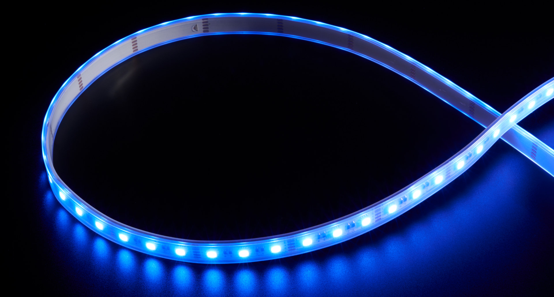
On the other end of the spectrum are cheap lightstrips which can be bought for as little as 5€ (less than 6 USD), and are usually controlled with an infrared (IR) remote. This means they can’t be controlled via the internet and can thus be not added to a smart home system. While there are different controllers available which allows controlling them via WiFi, they often require to use an app of the manufacturer and do not allow integration of the lights into one of the common platforms.
In the following post i will present two ways to connect these cheap light strips to the internet with minimal external hardware.
Emulating the remote control
The first option is to emulate the remote control by sending commands via IR. This has to advantage that no hardware hacking is required and the normal remote can still be used. But most of the limitations which exist with the normal remote (only a small number of colors, problems under direct sunlight) still exist.
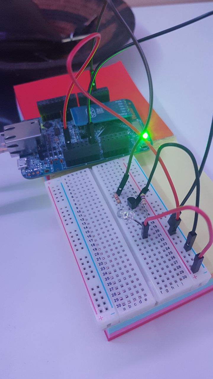
The IR-Light is generated using a cheap led (). To achieve a better performance, especially in sunlight i tried to get the maximum brightness out of the LED. This can be achieved by increasing the current thrue the LED, as the microcontroller i used for the project is only capable of delivering 25mA i decided to add a high-side-transitor which was connected to 5V, this also has the advantage that the 3.3V regulator is not as stressed and the chance of thermal problems is reduced. In retrospect the complete amplifier stage was most probably not necessary, as the microcontoller should be able to provide enough current.

The data is sent using amplitude modulation with the carrier beeing a square wave with a base frequency of 38222kHz, this form of modulation can be easily achieved by using PWM at the respective frequency and switching between 0% duty cycle and 50% duty cycle.
The baseband signal is encoded according to the NEC Protocol which uses pulse length coding. It starts with a 9ms burst, followed by a space of 4.5ms, next the 4 bytes of information are sent, first the address, next the inverse address, after that the command and as a last byte the inverse address. The inverse for the address and command is formed by flipping all bits.
| Name | Information | Encoding |
|---|---|---|
| Header | Start of the packet | 9ms High, 4.5ms Low |
| Address | The device to address, usually zero | See below |
| Not Address | ||
| Command | The color to choose, see below for more information | See below |
| Not Command |
The bytes are encoded least significant bit first, each bit starts with a 562.5us burst, if the bit is set the following space lasts 562.5us as well, else the space lasts 1687.5us.
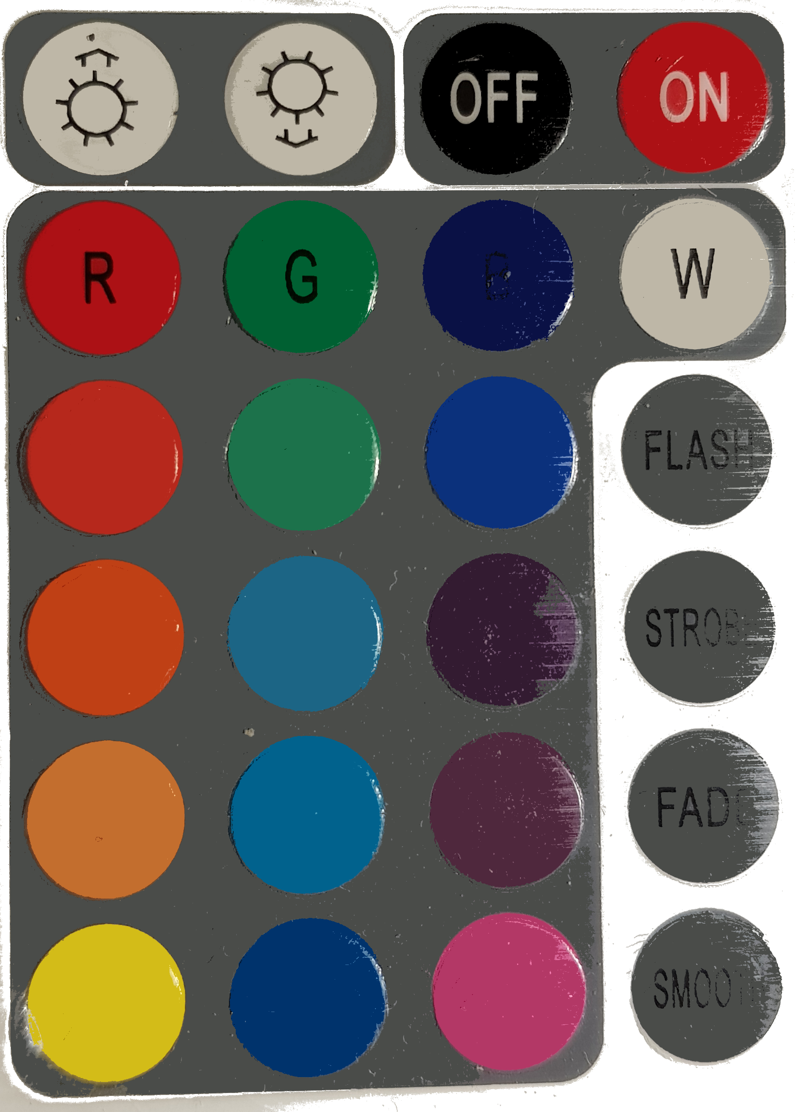
For both of my controllers the address was 0 and the command directly correspondend to the number of the key on the remote. With top left beeing zero and the following keys number in row-major-order.
I implemented the controller on an Freescale (nowadays NXP) FRDM-K64F using the Mbed Framework. The complete code is available on my github page.
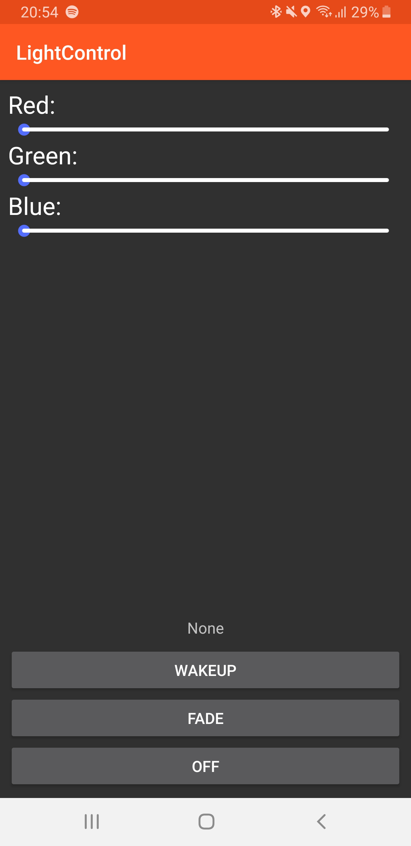
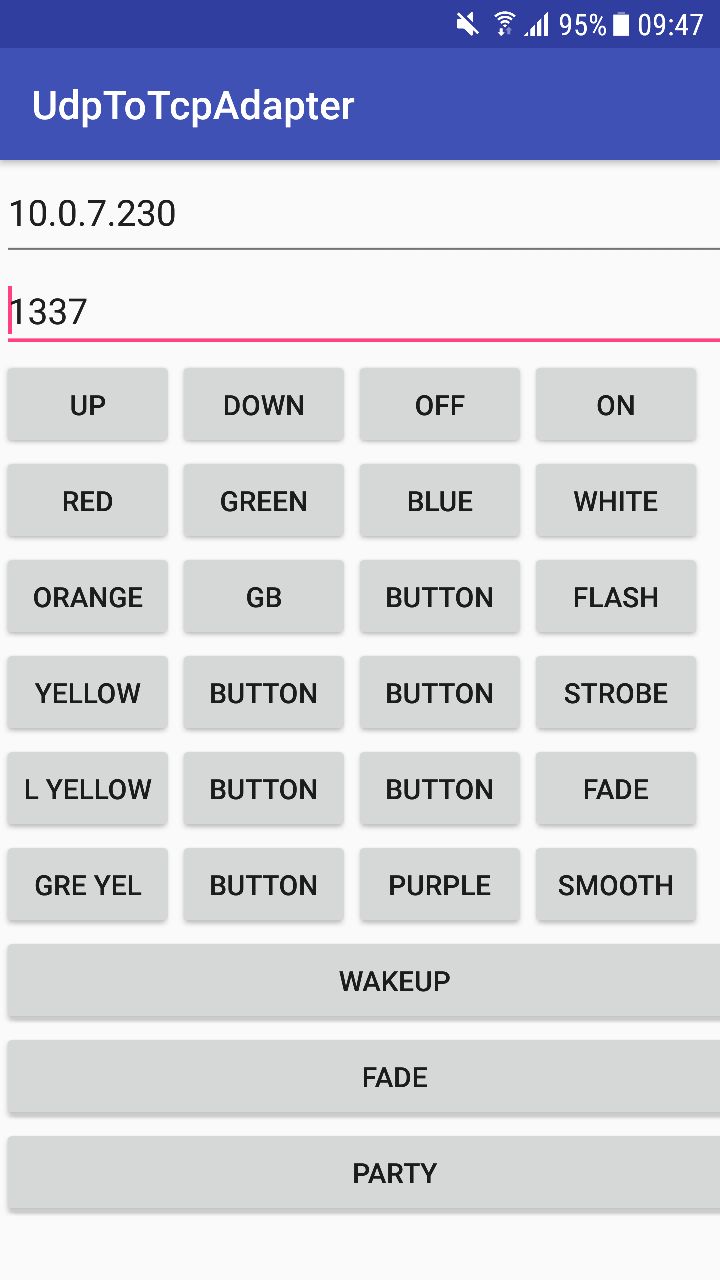
To control the light strip i wrote a little android app which sends the commands via UDP to the microcontroller. The app is also able to read the next alarm and trigger a wakup light.
Hacking the controller
The second option is hacking the original controller to send different signals. This means the amplifier stage is not driven by a chip which reads the IR signals but can be controlled with a separate microcontroller. This makes it possible to generate a lot more colors, with a commonly used 10-bit ADC, you can generate colors. The drawback of this solution is that it is necessary to hack the controller, this requires to cut some traces on the PCB and to solder wires onto the relevant pins.
As every controller is different it is difficult to explain how exactly to hack the controller. Usually the controller consists of some logic for decoding the IR signals and the amplifier which normally consists of three transistors, one per color. You need to find the traces which come from the control logic towards these transistors and cut them, this can be done with a sharp knife, for example a box-cutter or a x-acto knife. Please use a multimeter to verify that there is no connection before soldering wires onto the PCB. The easiest place to solder them is most probably the series resistors connected to the base of the transistor.
For my controller i soldered a second cable onto the output to able to control two strips from the same controller, before doing this verify that the controller is able to deliver enough current for both strips.
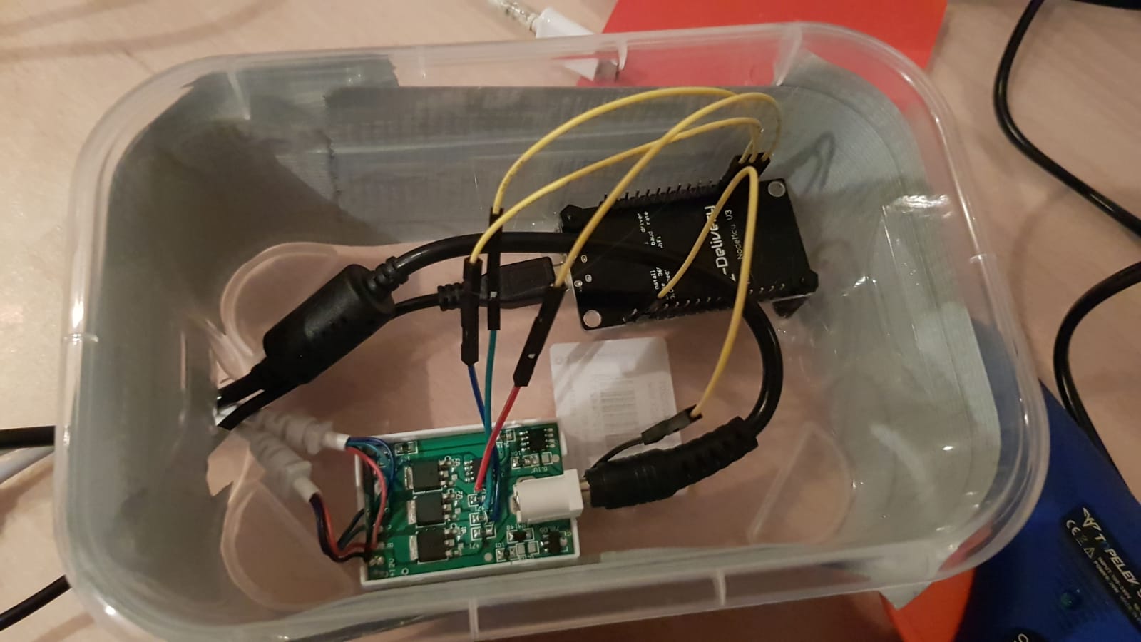
The controller is controlled using a Node-MCU ESP8266 Devboard. The board communicates via TCP, for a better abstraction RcLib is used as an application layer protocol. Each package consists of four channels with the following information:
| Channel | Information |
|---|---|
| 0 | Command: 0 means normale color, 1 means wakeup, 2 means fade |
| 1 | 10 bit red color information |
| 2 | 10 bit green color information |
| 3 | 10 bit blue color information |
The code running on the ESP-8266 can be found on Github at aul12/LightControlFirmware.
For my smartphone i adapted the app to be able to send all possible colors.